Solar-powered space flight
8. Other practical issues
[this page | pdf | references | back links]
Return to Abstract
and Contents
Next
page
8.1 Figure 11
includes an exhaust guide designed to keep the propellant from fouling the
mirror and vice versa. This is desirable because plume divergence can be very
large in space. With a mirror layout as per Figure 9, the inner edge of the
light rays travel along a line from circa (–0.08, 0.03) to (1.16, 0.30), which
crosses the y-axis at (0, 0.04). If we assume that the exhaust guide is
conical, forming the surface of revolution around the x-axis of the line
segment from (0, 0.04) to (1.16, 0.30) then it would have a surface area that
was about 43% of the overall collector area. It would therefore itself need to
be made of an ultra-low mass material. If  = –0.1 not –0.3 (but
  is still 1 and
  ) then the radius of
the hole in the middle of the mirror reduced by a factor of three. This reduces
the surface area of the exhaust guide to only about 12% of the collector area.
Such a design still has acceptable optical characteristics; its aperture factor
rises to 99%, its mirror surface area factor is 1.019 and its aberration factor
is 0.060.
) then the radius of
the hole in the middle of the mirror reduced by a factor of three. This reduces
the surface area of the exhaust guide to only about 12% of the collector area.
Such a design still has acceptable optical characteristics; its aperture factor
rises to 99%, its mirror surface area factor is 1.019 and its aberration factor
is 0.060.
8.2 Near the
rocket nozzle itself, the expelled propellant would of course be at a high
temperature, so this part of the exhaust guide is unlikely to be able to be
made of the same material as the mirrors. But this is where the exhaust guide
is narrowest, so it is also the part of the guide where there is least problem
in its mass per unit area being higher. Indeed, one can think of the exhaust
guide as in effect a very long extension to the rocket nozzle, which should
facilitate further adiabatic cooling as the ejected propellant travels along
it. This might increase the overall energy efficiency of the engine
compensating in part for the extra mass needed near to the rocket engine
itself.
8.3 Ejecting the
propellant along the positive x-axis through the hole in the main mirror
means that the thrust generated by the propellant ejection is likely to pass
through the centre of gravity of the vehicle (which is likely to lie along the
x-axis given the symmetric shape of the main mirror). Keeping the thrust always
about parallel to the axis of rotation should aid flight stability. However,
this also means that the positive x-axis would be in the opposite
direction to the sun. This means that the arrangement would operate most
effectively only when the sun was at a suitable inclination (i.e. approximately
45° to the vertical). Typical flight times would be sufficiently short in any
pre-orbital phase that the change in the inclination during flight would not be
particularly large in this context, so we can overcome this issue within the
pre-orbital phase by launching at suitable times of day (and within certain,
albeit relatively wide, latitudes of the equator). Once orbit is reached, a
more leisurely approach can be adopted, e.g. waiting until a part of the orbit
is reached when the sun is suitably positioned.
8.4 There are
also constraints on the payloads that such a vehicle could lift into orbit. For
example, suppose that the mirror weighs  kg and that the wires
joining the mirror to the main engine are on average at a 45° angle to the axis
of symmetry. The maximum acceleration experienced by the mirror might be
approximately
kg and that the wires
joining the mirror to the main engine are on average at a 45° angle to the axis
of symmetry. The maximum acceleration experienced by the mirror might be
approximately  . The force (parallel
to the axis of symmetry) that the wires joining the engine to the main mirror
would therefore need to apply to the mirror would be approximately
. The force (parallel
to the axis of symmetry) that the wires joining the engine to the main mirror
would therefore need to apply to the mirror would be approximately  kg ms-2.
Since the surface area of the mirrors is, say,
kg ms-2.
Since the surface area of the mirrors is, say,  m2 =
m2 =  ,
the length of these wires might be of the order
,
the length of these wires might be of the order  m. If we assume that
the wires are made of tungsten with a tensile strength of 3500 MPa and a density
of 19 × 103 kg m-3 then the mass of the wires would then
be at least approximately
m. If we assume that
the wires are made of tungsten with a tensile strength of 3500 MPa and a density
of 19 × 103 kg m-3 then the mass of the wires would then
be at least approximately  kg, and hence would
be at least as massive as the mirror if were greater than
circa 210,000 kg.
kg, and hence would
be at least as massive as the mirror if were greater than
circa 210,000 kg.
8.5 If we wished
merely to use solar power for orbital transfer then the practical issues
referred to above can be circumvented by using a different aplanatic two-mirror
layout, with, for example negative, positive (between 0
and 1) and  positive, see Kemp (2001).
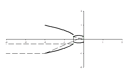
Figure 13 shows such a layout, if iterated to its extremities, derived from
positive, see Kemp (2001).
Figure 13 shows such a layout, if iterated to its extremities, derived from  ,
,  and
and  . The solid lines are
again cross-sections of the mirrors themselves, and the dotted lines are the
paths of light rays from the object to the image passing through extremities of
the available iterative process. Both mirrors are now ‘in front of’ the focal
point so propellant can now be expelled in a wide range of directions without
fouling the mirrors. This layout has an effective aperture factor of 90% and an
aberration factor of 0.02, i.e. not dissimilar to the ones described earlier.
Unfortunately, it has a mirror surface area factor of 2.86, i.e. its mass would
be about 2.8 times that of the mirror arrangement shown in Figure 8. It would
also need a boom to hold the mirror in tension parallel to the x-axis (further
increasing the mass of the arrangement) as well as needing to be rotated around
the x-axis to provide the necessary tension in the mirrors parallel to the y
and z-axes. If all that is required is a leisurely approach to orbital transfer
akin to the 15 – 30 days proposed for the SOTV then the extra mass per unit
collector area perpendicular to the sun’s rays would be less problematic, although
the collector arrangement would then be much less effective for any potential
subsequent solar sail use.
. The solid lines are
again cross-sections of the mirrors themselves, and the dotted lines are the
paths of light rays from the object to the image passing through extremities of
the available iterative process. Both mirrors are now ‘in front of’ the focal
point so propellant can now be expelled in a wide range of directions without
fouling the mirrors. This layout has an effective aperture factor of 90% and an
aberration factor of 0.02, i.e. not dissimilar to the ones described earlier.
Unfortunately, it has a mirror surface area factor of 2.86, i.e. its mass would
be about 2.8 times that of the mirror arrangement shown in Figure 8. It would
also need a boom to hold the mirror in tension parallel to the x-axis (further
increasing the mass of the arrangement) as well as needing to be rotated around
the x-axis to provide the necessary tension in the mirrors parallel to the y
and z-axes. If all that is required is a leisurely approach to orbital transfer
akin to the 15 – 30 days proposed for the SOTV then the extra mass per unit
collector area perpendicular to the sun’s rays would be less problematic, although
the collector arrangement would then be much less effective for any potential
subsequent solar sail use.
Figure 13. Mirror
layout arising from  ,
,  and
and 
NAVIGATION LINKS
Contents | Prev | Next