Solar-powered space flight
3a. Power required to reach earth orbit
ignoring atmospheric drag: Assuming that we launch vertically upwards, with
constant exhaust velocity
[this page | pdf | references | back links]
Return to Abstract
and Contents
Next page
3.1 The optimal use
of propellant for a solar-powered vehicle differs significantly from that
applicable with a conventional chemical rocket in any pre-orbital phase.
Typically, before orbit is reached, it is optimal for a chemical rocket to
accelerate as fast as possible (subject to any limits imposed by the
engineering of the vehicle itself). In contrast, a more leisurely approach is
optimal for a solar-powered rocket, because the longer the flight time the more
energy the solar power collector can collect.
3.2 For
solar-powered flight,  can be assumed to be
essentially constant (at least in the vicinity of the earth), unlike with
chemical rocketry where is proportional to
propellant used per unit time. In this section we ignore atmospheric drag even
though this assumption is obviously unrealistic. In section 4 we discuss the
impact of atmospheric drag.
can be assumed to be
essentially constant (at least in the vicinity of the earth), unlike with
chemical rocketry where is proportional to
propellant used per unit time. In this section we ignore atmospheric drag even
though this assumption is obviously unrealistic. In section 4 we discuss the
impact of atmospheric drag.
3.3 In each case
we will generally wish to work out how to minimise per
unit  , since all other
things being equal this is equivalent to minimising the area of the solar power
collector per unit final payload and hence presumably the mass of the
collector. The optimal approach will in turn depend on the choice of
, since all other
things being equal this is equivalent to minimising the area of the solar power
collector per unit final payload and hence presumably the mass of the
collector. The optimal approach will in turn depend on the choice of  , and therefore by
implication also on the ratio
, and therefore by
implication also on the ratio  , i.e. on the ratio
of propellant mass to vehicle plus payload mass.
, i.e. on the ratio
of propellant mass to vehicle plus payload mass.
3.4 Consider
first a hypothetical scenario where we launch using solar-powered propulsion
from the surface of the earth into earth orbit. One possible way of estimating
the power requirements of such a vehicle would be to assume that we would
accelerate vertically upwards until we reached orbital velocity. In these
circumstances (which would in fact fail to result in the vehicle reaching
orbit),  and the following
equations apply, derived from conservation of energy and momentum:
and the following
equations apply, derived from conservation of energy and momentum:

3.5 If, say,  =
5,000 ms-1 then flight metrics for various ratios of including the power
required per unit ‘lifted’ mass (i.e. mass of vehicle and engine at the end of
the trajectory, but not propellant) and the propellant to lifted mass ratios
are as per Table 1.
=
5,000 ms-1 then flight metrics for various ratios of including the power
required per unit ‘lifted’ mass (i.e. mass of vehicle and engine at the end of
the trajectory, but not propellant) and the propellant to lifted mass ratios
are as per Table 1.
Table 1. Flight characteristics to reach  for a range of
 , if propellant is
ejected vertically downwards at constant speed
, if propellant is
ejected vertically downwards at constant speed  = 5000 ms-1
|
 (kW/kg) (kW/kg)
|
Ratio of propellant
to lifted mass
|
(kW
per kg lifted mass)
|
Flight time to
reach orbital velocity (s)
|
Maximum
acceleration ms-2
|
|
150
|
4.8
|
872
|
69
|
316
|
|
100
|
5.3
|
625
|
105
|
228
|
|
50
|
6.6
|
379
|
217
|
137
|
|
40
|
7.6
|
342
|
276
|
123
|
|
30
|
9.2
|
307
|
376
|
110
|
|
25
|
11.2
|
305
|
459
|
109
|
|
20
|
14.6
|
313
|
585
|
112
|
|
15
|
23.3
|
364
|
799
|
132
|
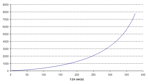
3.6 These
results do not initially look encouraging. The high maximum acceleration arises
because the rate of acceleration rises with time, see Figure 1 for one of the
above .
Figure 1. Plot of vehicle velocity and mass as a function
of time, if propellant ejected at a constant speed vertically downwards, if = 30 kW/kg.
NAVIGATION LINKS
Contents | Prev | Next