Solar-powered space flight
5c. Creating ultra-lightweight solar
power concentrators: Which rotationally symmetric aplanatic two mirror
arrangements are best for our purposes?
[this page | pdf | references | back links]
Return to Abstract
and Contents
Next page
5c. Which
rotationally symmetric aplanatic two mirror arrangements are best for our
purposes?
5.7 The most
effective layouts from our perspective appear to arise if  is positive,
  is negative (between
–1 and 0) and
is negative (between
–1 and 0) and  is negative, see Kemp (2003).
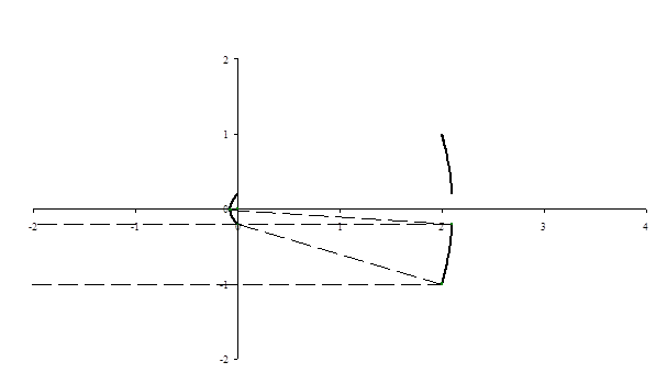
Figure 8 shows such a layout, if iterated to its extremities, derived from
is negative, see Kemp (2003).
Figure 8 shows such a layout, if iterated to its extremities, derived from  ,
,  and
and  . The solid lines are
cross-sections of the mirrors themselves, and the dotted lines are the paths of
light rays from the object to the image passing through extremities of the
available iterative process. This layout has an effective aperture area factor
of 96%, a mirror surface area factor of 1.03 and an aberration factor of 0.059.
It avoids having any of the rays of sunlight crossing the positive x-axis.
This is a desirable feature, as ideally propellant would be ejected along
approximately this axis, see later.
. The solid lines are
cross-sections of the mirrors themselves, and the dotted lines are the paths of
light rays from the object to the image passing through extremities of the
available iterative process. This layout has an effective aperture area factor
of 96%, a mirror surface area factor of 1.03 and an aberration factor of 0.059.
It avoids having any of the rays of sunlight crossing the positive x-axis.
This is a desirable feature, as ideally propellant would be ejected along
approximately this axis, see later.
Figure 8. Mirror
layout arising from  ,
,  and
and 
5.8 A possible
disadvantage of choosing the above values of and is that the larger
mirror is some way away from the image point, which would increase the mass of
wires joining this mirror to the main vehicle body. If instead we use  and
and  then the mirror
layout is as shown in Figure 9 and the main mirror would be nearer to the focal
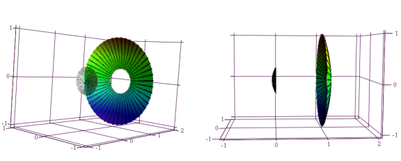
point (i.e. the origin) for a fixed collector area. Three-dimensional
perspectives of this layout are shown in Figure 10. The average aberration
factor improves to 0.020. However, the aperture area factor falls to 91% and
the mirror surface area factor rises to 1.13.
then the mirror
layout is as shown in Figure 9 and the main mirror would be nearer to the focal
point (i.e. the origin) for a fixed collector area. Three-dimensional
perspectives of this layout are shown in Figure 10. The average aberration
factor improves to 0.020. However, the aperture area factor falls to 91% and
the mirror surface area factor rises to 1.13.
Figure 9. Mirror
layout arising from  ,
,  and
and
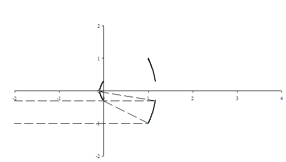
Figure 10.
Three-dimensional perspectives of mirror layout arising from , and
NAVIGATION LINKS
Contents | Prev | Next